


Data Center & Administrative Solutions
BMS Building Management System
Admin
18/08/2026
96 min read
What is a BMS system?
Building management system (BMS) is a comprehensive system that controls and manages many different devices in the building. The solution requirements of investors are completely met in terms of automatic control features for each mechanical and electrical system in the building:
- Air conditioning system includes Chiller, AHU, FCU, FFU, Cooling Tower
- Fire protection system.
- Electrical system.
- Water supply and drainage system.
- Elevator system.
- Heat pump system
Functions of the BMS system
-
Main features of the BMS system
The building management system allows:
Intervene and automate control of all energy consuming systems (ventilation, air conditioning, lighting...) to each location, each area of the building according to the requirements of the building manager and customers.
Allows intervention and automatic control of all mechanical and electrical systems of the building on schedule or in case of incidents.
Manage and control all security inside and outside the building, monitor and control people and vehicles entering and leaving, control intrusions, send security warning signals when there is an incident...
Automatically broadcast warning signals when problems occur (fire, explosion...)
Control the operating status of mechanical and electrical equipment in the building such as fans, air conditioners, lighting...
Manage and provide complete information about power consumption.
Provide periodic reports according to operational requirements.
Depending on the building's intended use, the BMS system will be equipped at an appropriate level.
-
Structure of the BMS system
The basic building automation BMS system includes 3 levels:
Operational and management level
System control level
Regional level – school level
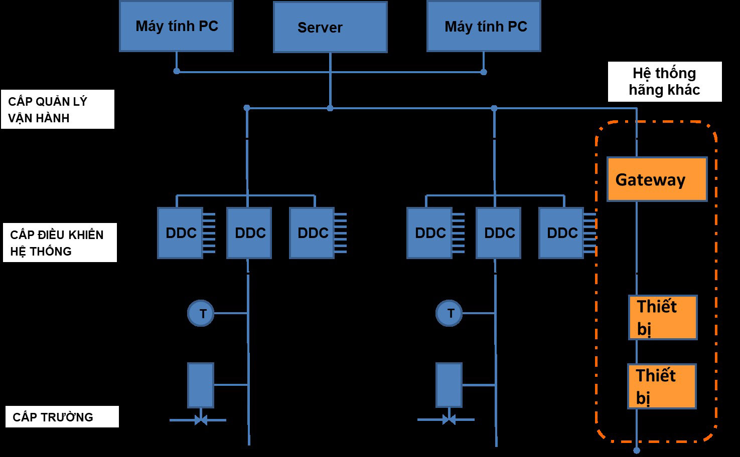
-
Benefits and necessity of BMS system
Automation, in recent years this concept has become familiar and is no longer a concept only used in specific areas of technical expertise. Automation has appeared in every field from production to serving daily life. The goal of automation technology is to build a system where humans are at the center, where humans set requirements and all operations to implement those requirements, depending on each field and each process, are undertaken by specific technical systems. The consequence is to liberate human labor and improve production efficiency.
Around the world, intelligent, automatic control systems have been applied very early and have shown undeniable important contributions. Construction today is almost indispensable without the deployment and application of automated systems. For industrial and civil construction projects, automated technical systems, collectively known as building automation systems, play an important role in maintaining an ideal working condition for the project, for people and equipment operating inside the building. A complete automatic system will provide the project with solutions to control and manage working conditions such as temperature, humidity, air circulation, lighting, security systems, fire alarms, technical equipment system management, save energy consumption for the project, and be more environmentally friendly. In Vietnam, in recent years it has not been difficult to recognize the contributions of automatic systems in industrial and civil works. The concepts of building management, building energy saving, environmental protection... are no longer so new. However, the level of application of these systems in general is still limited and not really deep and wide. This will change rapidly in the coming years, as the pace of modern construction increases, as building automation systems become more capable and reliable, and the benefits of applying these systems become increasingly clear.
Basis for investing in BMS system for the following reasons:
Firstly: BMS is highly practical, bringing clear economic efficiency.
BMS will automatically manage and optimize the equipment system to minimize energy consumption and increase equipment life by appropriately changing the load, time, timing, and frequency of operation of equipment such as (pumps, air conditioning systems, elevator systems...). This will contribute to reducing energy costs, reducing repair costs and fixing problems promptly.
BMS operates on the basis of programmable timetable events, thus requiring very little human intervention and supervision, reducing operating costs while ensuring more reliable operation of all technical systems.
BMS enhances building performance because it provides a very user-friendly interface for operators and managers through graphical interfaces. Users only need very little training time, do not need to understand the technical system deeply, but everything is still in the palm of their hand. This will reduce the cost of training and hiring high-tech experts.
The BMS system has high rationality and solutions, is optimal in terms of investment and operating costs and meets future expansion requirements.
Second: BMS is modern and future-oriented.
The BMS system always applies the most advanced scientific and technical achievements in the fields of electricity-electronics, telecommunications, and information technology to make these buildings smarter, more effectively managed and operated, bringing more convenience to people.
Third: BMS ensures safety requirements.
By centralizing information about all devices to the central processing unit, we can easily determine the status of the device, operate it, and fix problems such as power outages, failures, and fires. With an integrated security system, we can rest assured about the safety of users in the building and the security of personal information without losing comfort.
Wednesday: BMS enhances convenience for building users
The BMS is always transparent to employees working in the building. When using the BMS system, they no longer have to worry about turning off the lights or air conditioning when working hours are over, they don't have to manually adjust the temperature when they feel too hot or too cold, and they don't have to worry about losing their property in the event of an intruder or a fire. The BMS will automatically send notifications to the operator station and send messages to the manager via mobile network.
Integrating many features in devices helps users always feel comfortable. For example, you can always freely enter and exit 24 hours, easily set the temperature, set the time mode, monitor the outside weather status and management and operating information of the building.
Scope and method of integrating BMS system
Project: is a project with a large area for the purpose of examining and treating patients. Therefore, it is necessary to build a comprehensive integrated system to centralize control to help operate, manage and monitor the building in the most effective way. This building automation solution will aim to increase the building's operational efficiency by reducing energy costs, making it easier to operate and promptly handle incidents that occur, creating a comfortable, convenient and safe environment for people. BMS (Building Management System): is a modern, comprehensive building management and control system. For systems using specialized control software, investors' solution requirements are completely met in terms of control features as well as advanced technology applied to each device of the system. The BMS system has the ability to connect anywhere, any system, providing management capabilities with many options, improving employees' ability to work effectively. This is an open system capable of integrating with air conditioning and ventilation systems, fire alarm systems, safety systems, lighting systems...
For this project, with the requirements set forth, we propose the scope and method of integration and connection of mechanical and electrical items with the building management system as follows:
| STT | TECHNICAL SYSTEM
|
BMS APPLICATION | INTEGRATION PROTOCOL WITH BMS SYSTEM | |
| CONTROL | MONITOR | |||
| 1. MECHANICAL AND ELECTRICAL SYSTEM | ||||
| 1.1 | Air conditioning system includes Chiller, Cooling Tower, AHU, FCU,FFU
|
x | x | – Low level: Point-to-point connection (AI, AO, DO, DI) or Modbus RTU |
| 1.2 | System equipment: water pump, booster pump, inverter... | x | x | – Low level: Point-to-point connection (AI, AO, DO, DI) |
| 1.3 | Field device for measuring parameters and pipeline status: temperature, flow, pressure,... | x | Low level: Point-to-point connection (AI, DI) | |
| 1.4 | Fire alarm system | x | High: Modbus RTU | |
| 1.5 | Ventilation system: fresh air supply fan, exhaust fan, smoke extractor, toilet, booster fan | x | x | Low level: Point-to-point connection (AI, AO, DO, DI) |
| 1.6 | Elevator system | x | High: Modbus RTU | |
| 1.7 | Electrical lighting system | x | x | Low level: Point-to-point connection (DO, DI) |
| 1.8 | Generator, electricity meter | x | High: Modbus RTU | |
| 1.9 | Heat pump system | x | x | Low level: Point-to-point connection (AI, AO, DO, DI) |
Hardware and software interface of the BMS system
BMS system hierarchy
This project's BMS system includes 3 levels:
- Operational and management level
- Area control level – system
- School level
1. Operational, supervisory and management level
The operations, monitoring and management level is the highest level. Users can monitor and send control commands to each level below. Operating stations at this level are mainly PCs and Servers that manage and store data. Control Servers and PC Clients receive and process information from systems and perform control operations of systems located in the central control room.
BMS management software is installed on a computer with Microsoft Windows operating system platform.
BMS control software is specialized software in controlling and managing high-rise buildings. This software is capable of receiving information, monitoring the device's working status, performing system management and controlling device operations. The software is compatible with the systems participating in the integration. At the control computers, each operator is given a unique username and password corresponding to each person's access level to remotely control, monitor objects in the system, schedule equipment operations, monitor warnings - alarms and troubleshooting instructions. The interface between the operator and the system is a friendly, convenient and intelligent dynamic graphic interface.
At the branch operating station, the operator can completely perform the full functions of the central operating station if that operator is authorized.
The software has the function of supporting web access and has anti-hacker functions via web access.
In addition, BMS's central server runs on the Linux operating system, which is immune to viruses that violate and sabotage the center's programs.
Monitor and control the operating status of factory equipment using BMS system management software:
Allows system operation through an intuitive interface, along with alarm, scheduling, and reporting features.
The open system supports common communication standards in today's factory management systems such as: BACnet, Modbus, Lonwork, OPC...
– Uses energy management and power quality analysis; helps analyze and manage energy consumption more effectively, allowing analysis and evaluation of energy consumption information and coordination of all total substation energy consumption loads, thereby helping users come up with solutions to save energy, increase productivity and create a working environment that uses energy effectively.
Energy management software has the ability to track, monitor, and manage all energy in many different areas
Able to collect data and transmit data to the server, analyze and display all received data quickly
The software can retrieve all data according to each detailed content at the desired time period.
In case of power loss, connection loss, transmission error... the software immediately saves data at the time of disconnection. When reconnected, the software immediately updates new data and continues the monitoring process without losing data.
With a beautiful and vivid visual interface, data on the software is displayed in many forms such as graphs, detailed data tables that users need to compare...
Contributes to increasing the lifespan of equipment in the system, helping to reduce operating labor as well as minimizing internal problems that may occur in the system.
2. System control level - area
The control level is divided into two groups: network control level and field control level.
The network control level has the function of temporarily storing and transmitting information between the field controller and the central level. The network control level is made up of microprocessors with high communication and processing speeds. Structured as an independent processor, network controllers are able to work independently even when communication signals with central management are lost.
Field control level, also known as DDC direct digital controllers, are multi-function controllers used in monitoring signals transmitted from field devices such as temperature sensors, humidity sensors,...; Control equipment in the building such as FCU, HEAT PUMP,...
DDCs also support multi-function inputs, any input can be software defined:
- Digital input for status or alarm contacts
- Counter inputs for adding pulses from the measuring device.
- Analog inputs for quantities such as pressure, flow, and position.
- Digital outputs for on/off control.
- Analog outputs for motor control, and primary device control capabilities.
Along with the DDC controller are I/O expansion modules that fully integrate digital and analog signals to receive and control field devices with corresponding signals...
3. School level
Field-level devices include sensors such as pressure sensors, temperature sensors, humidity sensors...; Executive devices such as proportional control valves, On/off control valves... Depending on the characteristics of each field device, the types of signals that will be received to the DDC will be corresponding to the DDC and data will be transmitted to the center for processing.
Hardware devices
1. Server
System servers include several servers with a client-server architecture. The number of system servers will vary depending on system requirements. Servers include system management servers and data storage servers. The servers use the open source Linux operating system.
System Management Server (Supervisory Controller – SVC)
The system management server collects information from main devices (for example, DDC) and then performs display, installation, operation, storage, and advanced control functions for the entire system management process (point data, programs, etc.) and delivers it to the software installed on client computers. The server supports up to 5 client computers accessing at the same time.
– Open system supports common communication standards in today's building management systems such as: bacnet, modbus, lonwork, opc...
– Origin: G7
Table 4.1. System management server specifications/specifications
| STT | Specifications/Specifications |
| Controller | Compact industrial, integrated network controller. |
| Operating system | Linux |
| Communications | BACnet/ IP (Ethernet: 10BASE-T/ 100BASE-TX), 1 channel |
Client PC
A client computer is a computer with software to access databases stored on system servers. Client computers are often installed in surveillance rooms to manage the entire building. It monitors the following features:
- Monitoring: status, alarms and measurements at each location.
- Operation: remote control on/off .
- Output data: operating status, alarm status and measurement data.
- Data analysis: operating status, alarm status and measurement data.
Up to 5 client computers can access the server at the same time.
The client computer needs the following configuration:
- Operating system: Windows®.
- Processor: Intel® Core i5-5200U or higher.
- Graphics card: Intel® HD 5500 or higher.
- Main capacity: 8.0GB or more.
- Storage capacity: 40.0GB or higher.
- Resolution: Full HD (1920×1080) with 16:9 ratio (can be set in a range from WXGA(1366×768) to 4k(3840×2160)).
- Software: Microsoft excel 2016 or higher, SVC software.
Printer
Any printer with an available USB connection can connect to the system's network. The printer driver must be compatible with Windows 10 or later.
Area level controller
Direct Digital Controller (DDC)
DDC direct digital controller performs control of all or several devices. Control operations will be self-sustaining allowing for continuous control even if other parts of the system fail. Data transmission is performed between client computers and the building high-level controller. Client computers will receive changes in setting values or control results.
| Category | Technical specifications | ||
| DDC controller |
BACnet standard |
Transfer data | Transmission by electric current |
| Internal memory | SDRAM 256MB, Flash ROM 32MB, SRAM 2MB | ||
| Connection distance | 1000m | ||
| Remote connection | Maximum 25 units | ||
| Material (cover), color | PPE plastic | ||
To connect to field-level devices such as temperature and humidity sensors, in addition to the controller, we need IO Modules as shown in the picture.
Origin: Asia.
Field Grade Devices
Sensor for measuring room temperature and humidity
Use a thermistor sensor to measure temperature. Designed to be installed on narrow ceilings. Sensing range from 0° C to 60° C with sensing accuracy ± 0.3° C. This sensor is suitable for all applications in the environment of office buildings, commercial buildings...
Water pipe pressure sensor
The differential pressure sensor has the following parameters:
- Measuring range: from 0 to 2500 kPa.
- Output signals have the following formats: 0-20mA, 0-5V, 0-10V,...
Water temperature sensor
Pipe-mounted sensor, used to measure and check the water temperature on the chiller's supply/return water line for the purpose of facilitating the chiller control process.
Pressure sensor
Sensor used to measure the pressure of hot, cold water, salt water, lubricants, steam, air and other liquids. Converts the measured value into an electrical signal from 4 to 20 mA DC.
Water level sensor
Water level sensor used in water supply and drainage systems, fire protection, used to measure the water level at the tank location of the system to ensure the water level is always in a safe position to operate the gas system in case of problems as well as for daily use.
Oil level sensor
Oil level sensor used in generators, used to measure the oil level at the generator's tank location to ensure the oil level in the tank is always in a safe position to operate the gas system during a power outage.
Flow switch
Flow switch used in water supply and drainage systems, installed behind the water pump's push head, is used to determine whether the pump operates when there is a signal from the system whether water is circulating in the pipes or not, ensuring the most accurate and efficient operation of the pumping system.
Air quality sensor
Air quality sensor used in ventilation systems, installed inside spaces where unwanted toxic gases may be generated. Used to detect polluted gases in the installation space and control the exhaust fan system to suck the amount of polluted air in the installation space out of the polluted air discharge area.
CO2 sensor
CO2 sensor is used to monitor CO2 concentration in the operating room, installed on the wall to monitor CO2 concentration and control the AHU to absorb CO2 gas and regulate the operating room environment to ensure safety and cleanliness.
Air pressure sensor
Room air pressure sensor is used to monitor air pressure in operating rooms, where clean air and stable pressure are needed to avoid environmental conditions that affect surgery. The air sensor will be linked with the AHU system to regulate the operating room environment to ensure safety and cleanliness.
Dirty filter indicator
Used in air filters of AHUs and FFUs to help operators know when to change filters in AHUs and FFUs to avoid the situation where the installation area is not well ventilated.
Overheat alarm
An overheat alarm is installed in the AHU, used to warn that the temperature of the dryer in the AHU exceeds the permissible setting level.
Differential water pressure sensor
Used in the Chiller system to regulate the amount of water in the Chiller pipes to ensure safe operation of the Chiller system, avoiding wastage or pressure incidents exceeding the allowable level of the Chiller pipes.
Outdoor temperature and humidity sensor
Outdoor temperature and humidity sensors are installed in the operating room to monitor and from there have a basis for controlling the temperature in the operating room to achieve a suitable environment for operations or surgeries.
Smoke alarm sensor
Installed on the AHU is used to warn that the air supplied to the AHU has smoke, affecting the operating rooms, and the operator has the necessary treatment plan.
Water flow meter
Used in the Chiller system to help the operator as well as provide a condition for the Chiller system to automatically regulate capacity according to intended use and water flow, avoiding unnecessary waste.
Water and electrical conductivity meter
Water conductivity meter is used in the Cooling Tower system. The water conductivity meter is installed to measure water conductivity, from which the system will decide the discharge and replenishment of water for the Cooling Tower system.
Wastewater tank water level sensor
Installed in the treated wastewater tank, because the wastewater is not clean, a float sensor is used to ensure operation.
Hot water level sensor
The sensor is used to measure the water level in the hot water tank because hot water conditions have high temperatures, conventional rod sensors cannot be used, ensuring the operation of the BMS system.
Air flow meter
Air flow meter is used to measure air flow into the operating room. Serves as a condition for the system to adjust and balance temperature and humidity in the operating room. Ensure operating conditions.
Thermostat controls the FCU
Used to control wind speed, valve opening, operating mode, etc. Connected to the BMS system via Modbus RTU communication.
Control screen in the operating room
Installed in the operating room, it is convenient to monitor operating room conditions and adjust operating parameters to suit necessary cases.
Software
Building management system (BMS) includes software applications that allow management, monitoring and control.
User Management:
BMS software allows access to many operators in the system. Operators have different tasks for each specific application and specific equipment.
Operators with different tasks are granted different levels of access, monitoring and control rights for each specific application and specific device.
When operators access control operations on the computer of the BMS system, the time and control operations of the devices are recorded over time.
Operation, warning and alarm levels can be classified.
Save Record
Saves and displays a record of user commanded operations. The items recorded and displayed are:
– Date (year, month, day) at the time of operation.
– Time (hours, minutes, seconds) at the time of operation.
– Member ID.
Types of recorded operations include display, setting, printing, display change, cancel, button name pressed, dialog box name opened, operation content, input content and settings, device ID, point ID, point name, program name, and whether the operation was successful or not. Maximum storage of records is up to 1,000,000 records. Activity records can be saved as CSV and stored on the client computer.
Obtain information:
- Obtain all environmental parameters, information about the operating status of devices, information about the operation of systems, and the coordination of operations of systems connected to the BMS.
- Store and process information and can use this information long-term according to management requirements.
- Measurement and summary values are displayed on the screen, daily reports on the operation of equipment in the building. Users can record daily reports automatically or manually as PDF files, no paper required.
Report Date
Daily reports for the last 40 days including the current day can be displayed and printed.
The daily report displayed on the screen can also be in CSV format.
Printable data includes the following 3 types:
– Hourly report data includes the total of minute-by-hour values (aggregate value) or the following optional values: maximum, minimum, average hourly minute value, and hourly value (measured value).
– Daily report data includes the total values for each hour of a day (for the current day and the previous day), the load factor (aggregated value), and the maximum, minimum, average, readings for each hour of the day (Specify the value needed to print).
– Monthly report data includes the total values of each day in a month, the load factor (aggregate value), and the maximum, minimum, and average values of each day in a month (Specify the values needed to print. Monthly report data is printed after daily report data is printed).
Monthly reports can be saved manually or automatically in PDF format.
Monthly Report
Monthly reports for 13 months including the current month can be displayed and printed as desired. Monthly reports displayed on the screen can also be saved in CSV format.
Printable data includes the following 3 types:
– Daily report data includes the total values for each hour of a day (for the current day and the previous day), the load factor (aggregated value), and the maximum, minimum, average, readings for each hour of the day (Specify the value needed to print).
– Monthly report data includes the total values of each day in a month, the load factor (aggregate value), and the maximum, minimum, and average values of each day in a month (Specify the values needed to print. Monthly report data is printed after daily report data is printed).
– Annual report data includes the total values of each month in a year, the load factor (aggregated value), and the maximum, minimum, and average values of each month in a year. (Specify the required value for printing. Annual report data is printed after monthly report data is printed).
Monthly reports can be saved manually or automatically in PDF format.
Annual Report
Annual reports for the last 10 years including the current year can be displayed and printed very conveniently. The annual report displayed on the screen can be saved in CSV format.
Printable data includes the following two types:
– Monthly report data includes the total values of each day in a month, the load factor (aggregate value), and the maximum, minimum, and average values of each day in a month (Specify the values needed to print. Monthly report data is printed after daily report data is printed).
– Annual report data includes the total values of each month in a year, the load factor (aggregate value), and the maximum, minimum, and average values of each month in a year (Specify the required values for printing. Annual report data is printed after the monthly report data is printed).
Edit Report Format
The report format can be freely edited by the user if necessary. Members can change, add, delete predefined lines or add merge cells to suit each project's requirements. BMS will convert report formats when there are edits.
Graphics:
- BMS control software provides a graphical display to manage warning signals and technical alarms. All system error information and device error reports of systems connected to iBMS will be displayed on this error screen. The BMS divides the technical alarm level into 6 different levels and the importance levels of these warning signals are shown by the system by standard color changes.
Example: Color of error warning signals of control points in each specific state. (The colors of the warning signals are set by the administrator; the example below is an adjustment).
- When the device is in normal state, the color is Blue.
- When the device is in operation, the color status changes to Green.
- When the device reports an error, the color status changes to Black
- When the system has no connection to the “Point” device controlling the device is Brown
- There is a “get ready” level fire warning in Purple color
- There is a "real fire" fire warning in Red color
- The BMS control software supports alarm warnings with a beeping siren, which is a sound to remind operators when they are not observing the control screen.
